Vertical Take-Off and Landing (VTOL)
There are more and more applications of unmanned aerial vehicle (UAV) in civil life. UAVs have different configurations as well as sizes. Among different kinds of UAVs, vertical take-off and landing (VTOL) unmanned aerial vehicle (UAV) is a kind of UAV that interests people in UAV field due to its good flight performance. VTOL UAVs combine both the advantages of copters and fixed wing aircrafts, which is using little take-off and landing space and long range and endurance. With the advantage of adding no extra mechanism and mass into the aircrafts, tail-sitter is chosen as the research target among different kind of VTOL. However, though tail-sitters have the advantage of simple configuration, it is difficult to build up a mature control system in the current stage due to the highly coupled nonlinear system. In order to developing a reliable control algorithm for the tail-sitter, the aerodynamics of a specific tail-sitter were studied using experimental method and the real-time hardware-in-loop (HIL) simulation system of have been built. The corresponding database for HIL was extended to full angles of attack to meet the demand of the HIL system (Figure 1). The tail-sitter UAV system consists of 4 main components as shown in Figure 2: 1) airframe, 2) navigation system, 3) remote control and 4) data link. The dynamic simulation was developed in Simulink, and the real-time application was developed based on the Simulink Desktop Real-Time Kernel, which supports real-time performance at sampling rates up to 1 kHz (Figure 3). The HIL simulation system was validated by using the initial condition from the real flight log from both in-door and out-door test and then compared the results to the corresponding later flight log data (Figure 4, Figure 5).
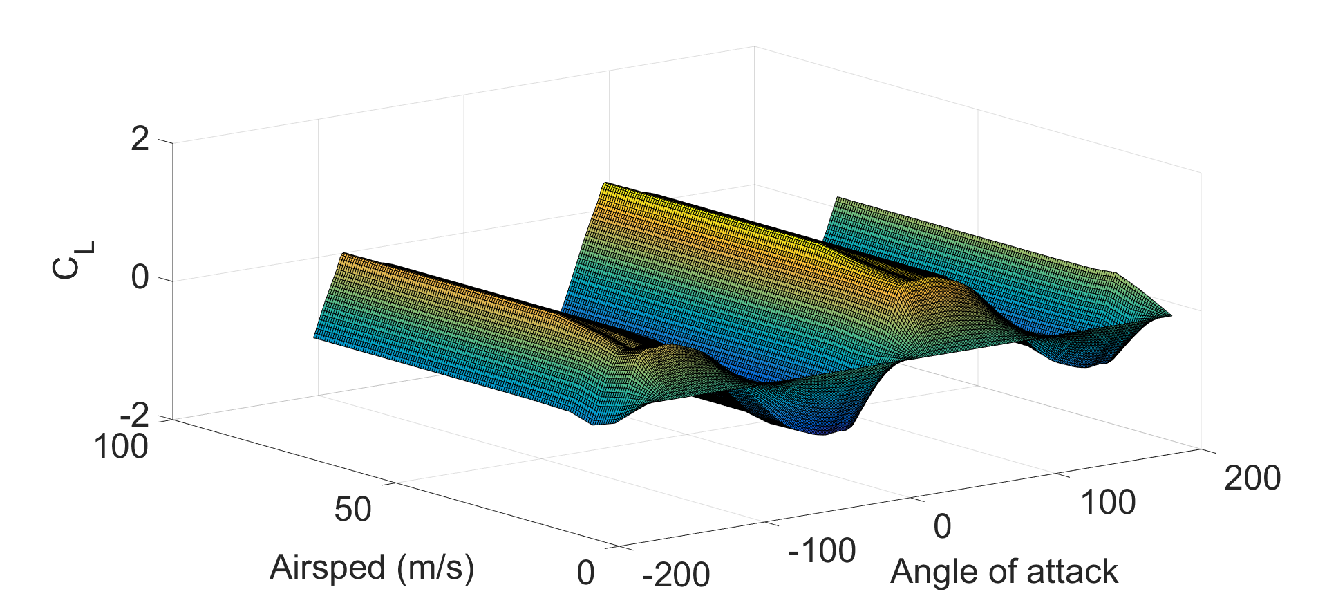
Figure 1. Lift coefficients from -180°-180° flap=0
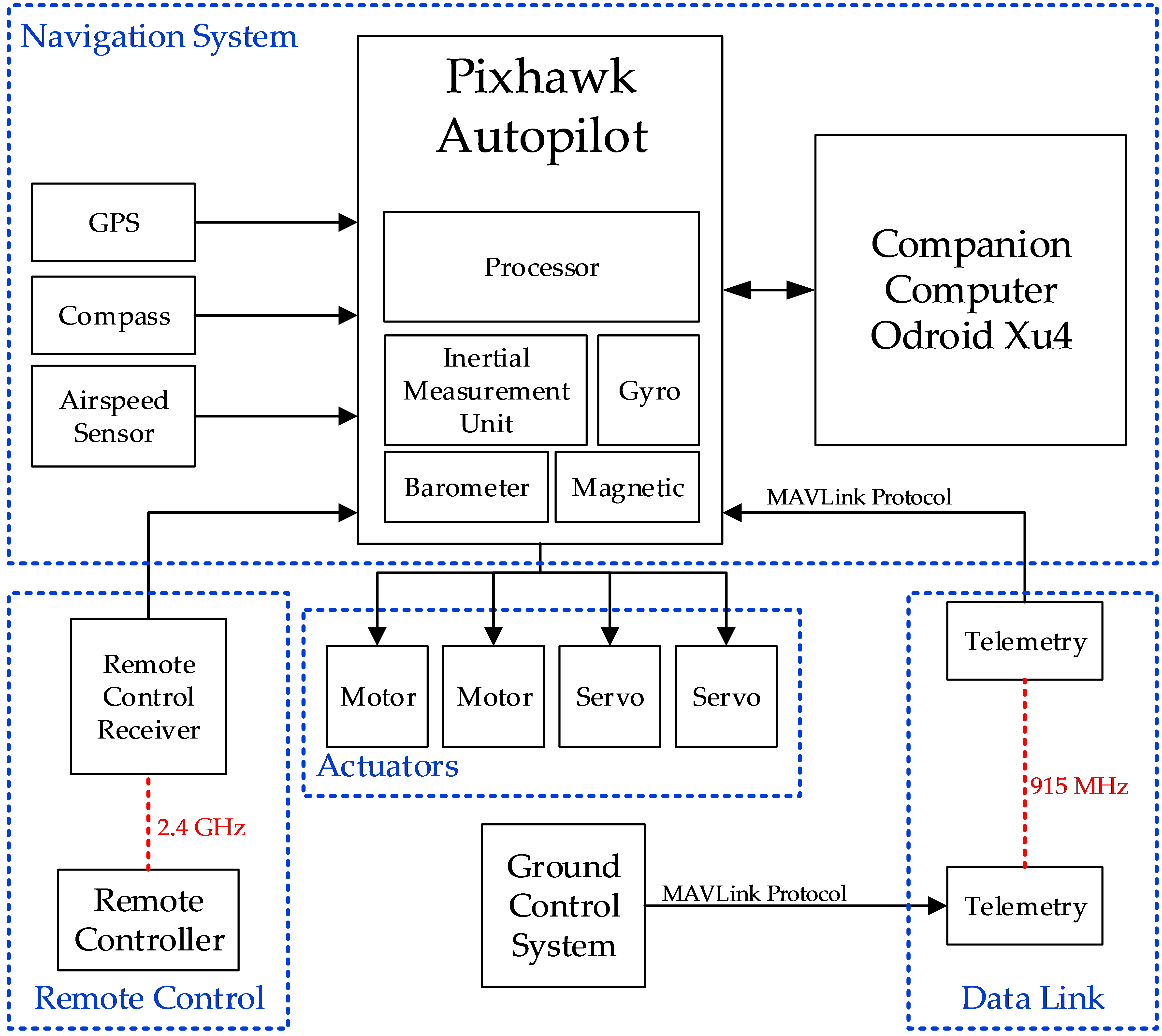
Figure 2. Schematic diagram of the UAV system
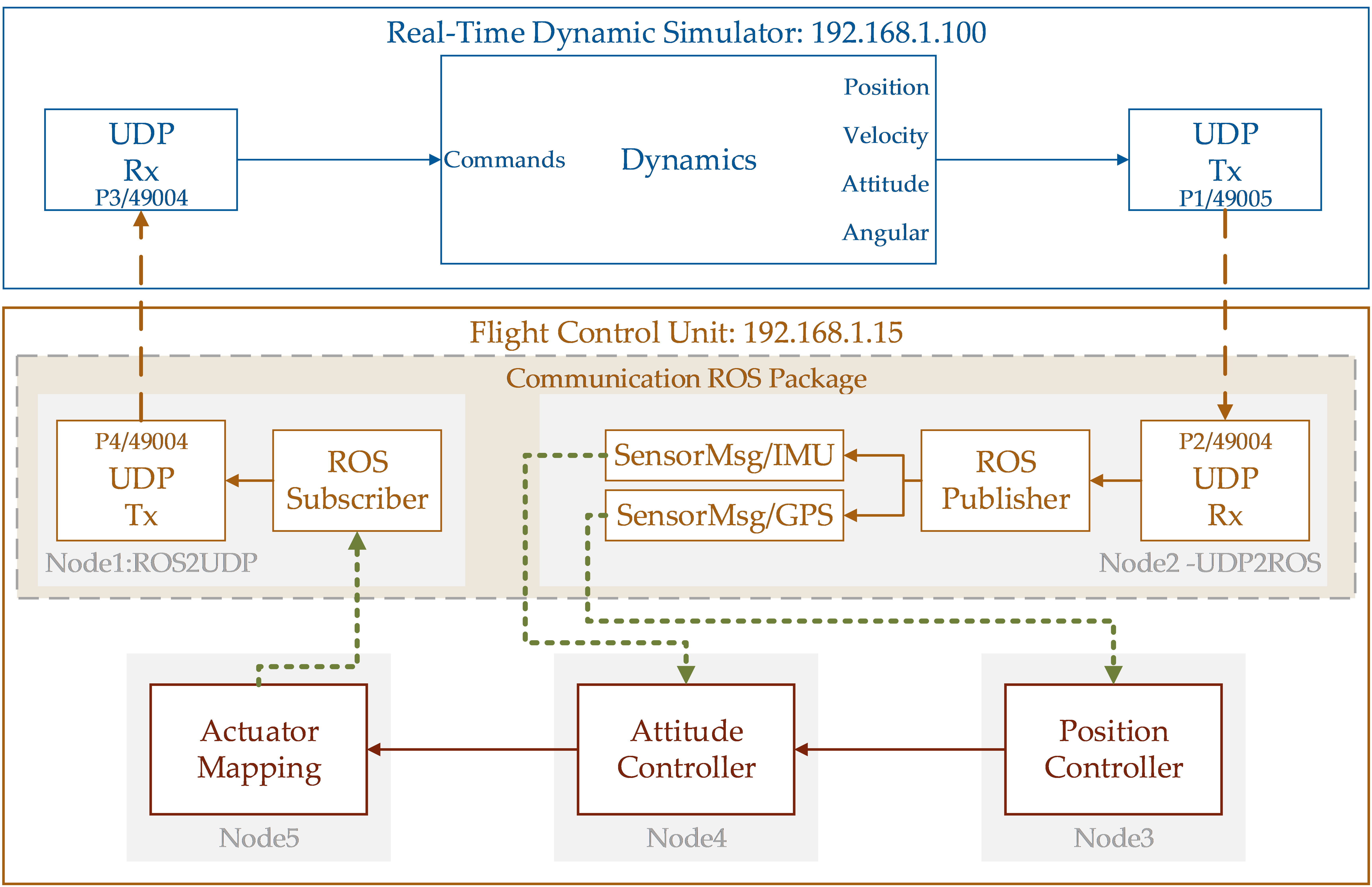
Figure 3. Real-time aerodynamic model in Simulink simulator
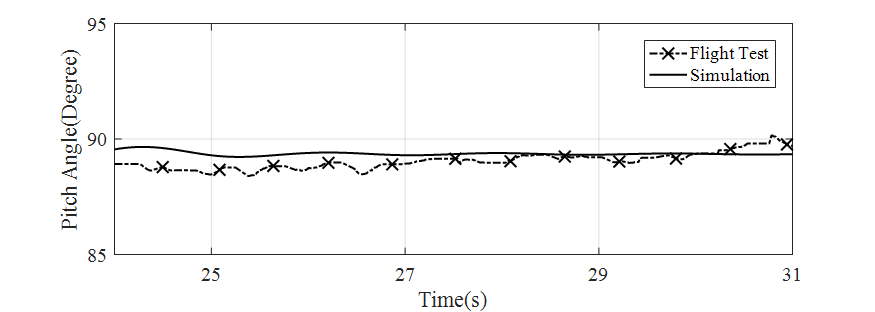
Figure 4. Comparison of pitch angle control results between the indoor flight test and the simulation

Figure 5. Attitude results from the outdoor flight test segment and simulation