Hypersonic Transition
Laminar-to-turbulent transition generates significant increase in viscous drag and heat flux, leading to severe restrictions on the performance and thermal protection system of hypersonic vehicles. Estimate for the National Aerospace Plane (NASP) shows that the pay-load-to-gross-weight ratio would nearly double if the vehicle boundary layer is fully laminar, compared to fully turbulent .Early transition also causes higher heating, which then requires an increased performance thermal protection system (TPS), active cooling, or trajectory modification, leading to higher cost and weight of hypersonic vehicles. In order to investigate the mechanism and possible transition control methods, extensive works have been carried out in our lab.
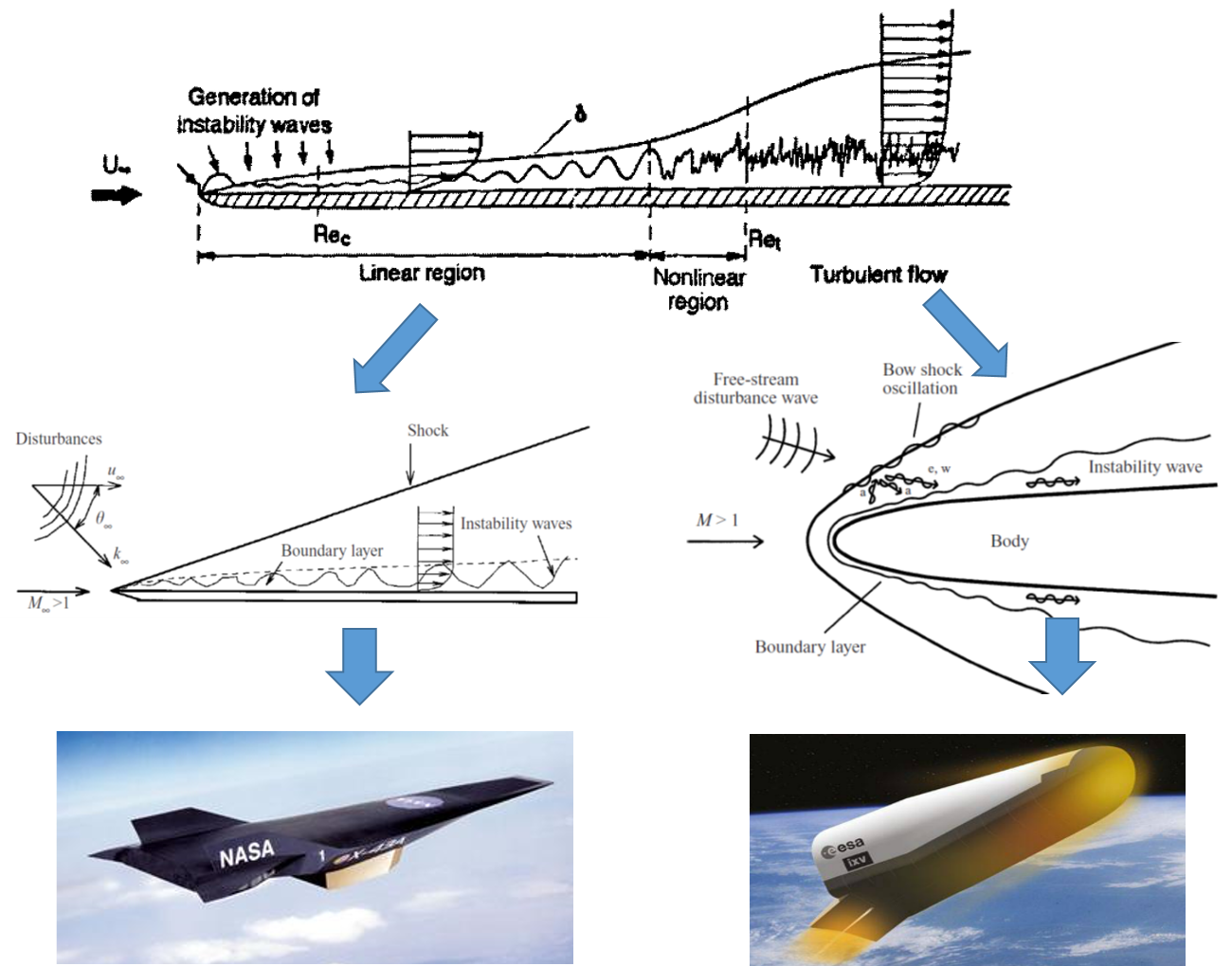
Transition phenomenon
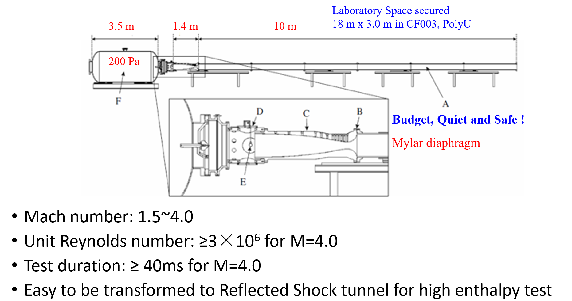
Wind Tunnel-Ludwieg Tube
Numerical Wind Tunnel
For simple configurations, such as flat-plate, cones and corners, high-order accuracy schemes are employed to directly simulate the stability and transition phenomena. We also developed in-house code for engineering transition prediction, including empirical models, transition models and large eddy simulation.
A.Study on the effect of local heating/cooling
A suction-blowing disturbance is introduced at the leading edge. When the disturbance is fully developed, a heating /cooling element is active.
Local heating effect on the stability
Pressure evolution
Fluctuating pressure evolution
Wall fluctuating pressure evolution
Local cooling effect on the stability

B. Stability study on the effect of roughness
A suction-blowing disturbance is introduced at the leading edge. The animation below shows effect of roughness on the evolution of unstable waves.

Fluctuating pressure evolution, with pressure contour as the background
C.Stability study on the effect of wavy wall
A suction-blowing disturbance is introduced at the leading edge. The animation below shows effect of waviness on the evolution of unstable waves.
Fluctuating pressure evolution, with pressure contour as the background
D.Stability study on the effect of ART material
We also focus on the stabilization effect of acoustic rainbow trapping metal-material (ART) on hypersonic boundary-layer.
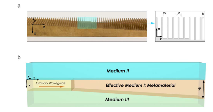
Fluctuating pressure evolution, with pressure contour as the background
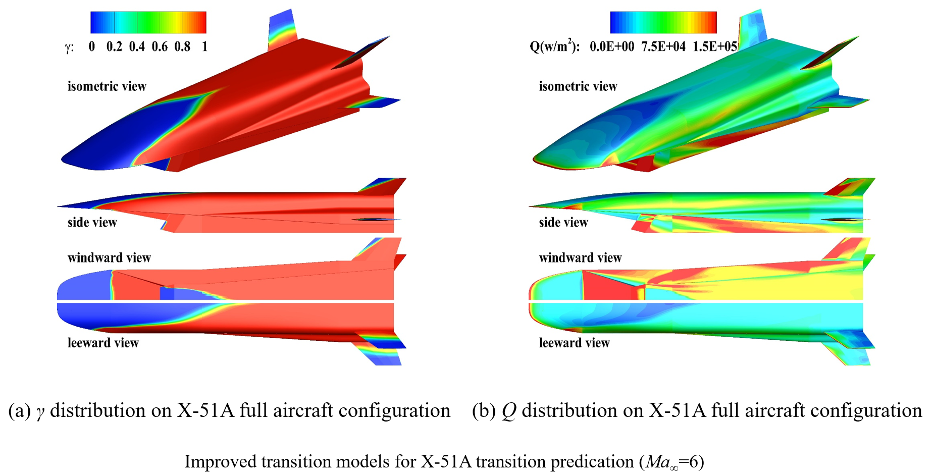
E.Engineering predication
Linear Stability Analysis
In order to help interpret the characteristics of instability, we also developed LST codes to calculate the unstable waves.
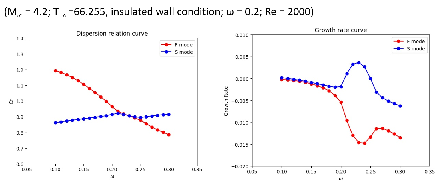
Discrete modes F and S evolution
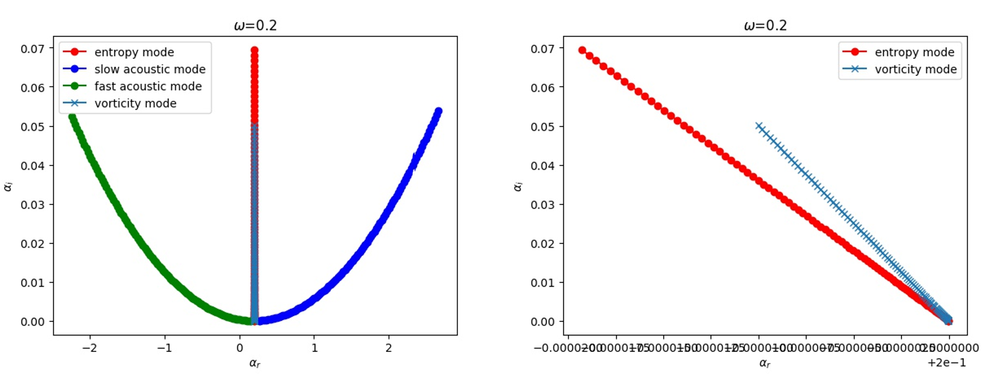
Discrete modes F and S evolution
F. Theoretical impedance model
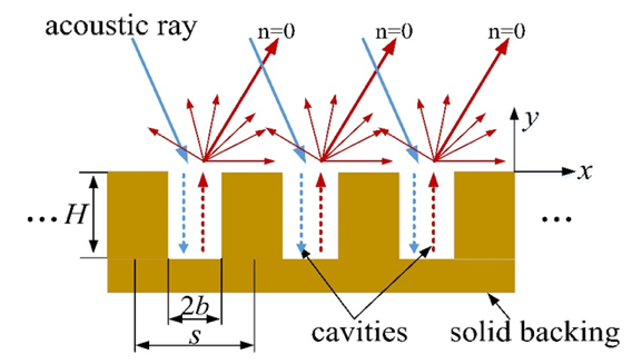
Reflection of acoustic waves
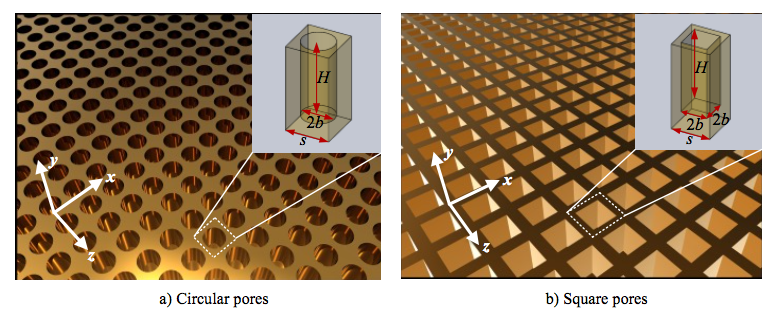
Schematic illustrations of porous coatings with pores of different cross-sections.
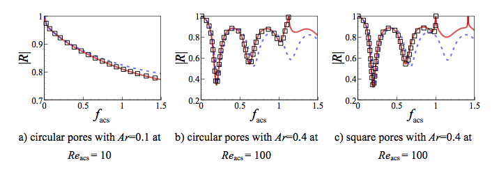
Comparison of reflection coefficient amplitude from COMSOL (black square), the proposed model (red solid curve) and Fedorov’s model (blue dashed curve).
G. Impedance-near-zero metasurface
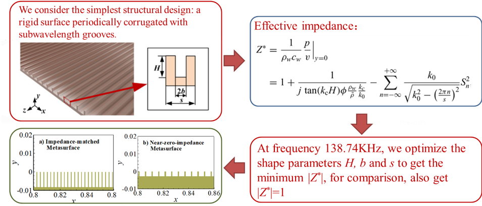
How to obtain the impedance-near-zero metasurface
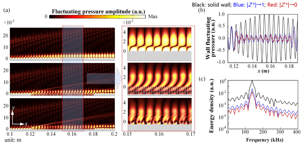
Direct numerical simulation of fluctuating pressure fields when hypersonic flow passes the metasurface. Problem formulation is as for Fig. 2(a) except that the metasurface is only located at x = 0.12-0.18 m to save computational resource. (a) Fluctuating pressure amplitude contours for rigid boundary (upper), impedance-matched metasurface (middle), and impedance-near-zero metasurface (lower), with the corresponding zoom-in views shown in the right column. (b) Comparisons of fluctuating pressure along the surface (y = 0) for different boundaries. (c) Comparisons of energy density at (x, y) = (0.16 m, 0 m) for different boundaries. In (b) and (c), the black line represents data for the rigid boundary, the blue line for the impedance-matched metasurface, and the red line for the impedance-near-zero metasurface.
Fluctuating pressure evolution along the impedance-matched metasurface
Fluctuating pressure evolution along the impedance-near-zero metasurface